Submission Components:
Library:
- Hard copy of Final Report with Hard Cover
- Soft copy of:
* Abstract.txt
* Final Report.pdf
* Technical Report .pdf
* Schematic & Program .rar
* Poster.jpg
* Picture.jpg
* Video.flv
Upload at http://rps.bmi.edu.my/fyp/submission/S112/Degree/51210209015 :
- Soft copy of:
* Abstract.txt
* Final Report.pdf
* Technical Report .pdf
* Schematic & Program .rar
* Poster.jpg
* Picture.jpg
* Video.flv
Submit at FYP Advisor ( Mr. Tan Yee Chyan )
- Hard copy of Final Report with Hard Cover
- Claim Receipt
NOTE: ALL OF THE SOFT COPY CAN BE FOUND AT
http://rps.bmi.edu.my/fyp/submission/S112/Degree/51210209015/index.php?studName=MUHAMMAD%20NADIY%20BIN%20ZAIAAMI&studId=51210209015
Friday, 18 May 2012
week 14: Presentation Day
Presentation Day:
assessor 1: Miss Shairah Wazir
assessor 2: Mr. Zulkifli B Mahmoodin
on presentation day, everything going smoothly .
student can answer the question confidently.
there are a lot of technical question.
Overall Project:

Video:
Poster:


assessor 1: Miss Shairah Wazir
assessor 2: Mr. Zulkifli B Mahmoodin
on presentation day, everything going smoothly .
student can answer the question confidently.
there are a lot of technical question.
Overall Project:

Video:
Poster:


week 13: Problem Occour
1- Capacitor
At the reset button, it have to make a parallel connection with the 220pF (104) ceramic capacitor. It is because to prevent multiple pulse give to the PIC16F877A. If the users press the reset button once, user has to wait the capacitor to be charged up before the second press. It is the law of capacitor to be charge and discharging. The knowledge of electronic components that student learn on previous semester have been applied.

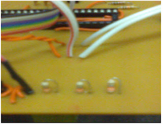
2- LED and Resistor Priority
Simulation and actual device is not same. On the simulation, there are no tolerance and there are no disturbance. Everything are considered to be perfect. On Figure 3.9 there are a mistake that student do. For all know, the function of resistor is to prevent over current to LED. In this case, the circuit have to modified manually to avoid from making a new PCB. The arrangement of resistor and LCD are changed.
3- LCD
There are many type if 16x2 LCD. Each type of LCD have their own datasheet and connection. LCD must be grounded according to it’s pin. Wrong connection will display nothing except black and white screen on LCD. At first, student buy a VCM162A LCD. The result of the system is the LCD display a creepy character but it is working great on the other type of LCY which is JHD162A. With the insufficient time, the new LCD are replaced.

At the reset button, it have to make a parallel connection with the 220pF (104) ceramic capacitor. It is because to prevent multiple pulse give to the PIC16F877A. If the users press the reset button once, user has to wait the capacitor to be charged up before the second press. It is the law of capacitor to be charge and discharging. The knowledge of electronic components that student learn on previous semester have been applied.

2- LED and Resistor Priority
Simulation and actual device is not same. On the simulation, there are no tolerance and there are no disturbance. Everything are considered to be perfect. On Figure 3.9 there are a mistake that student do. For all know, the function of resistor is to prevent over current to LED. In this case, the circuit have to modified manually to avoid from making a new PCB. The arrangement of resistor and LCD are changed.

3- LCD
There are many type if 16x2 LCD. Each type of LCD have their own datasheet and connection. LCD must be grounded according to it’s pin. Wrong connection will display nothing except black and white screen on LCD. At first, student buy a VCM162A LCD. The result of the system is the LCD display a creepy character but it is working great on the other type of LCY which is JHD162A. With the insufficient time, the new LCD are replaced.

week 12: Soldering


1- soldering Iron
2- Sucker
3- wet spounge
4- hand drill


1- drill the pcb stand to make a task easier (drilling&soldering)
2- put the PCB stand
3- start drill the hole for components
4- solder all of the components according to the circuit design
week 11: Final PCB layout & Atching


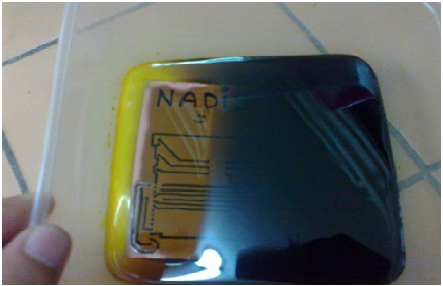

Step to make a PCB:
1- print layout on Oscilloscope Plastic ( black and white)
2- iron the plastic on PCB board
3- adjust with marker the spot that did not have connection
4- boil a plain water
5- put an atching liquid in the Tupperware and add some hot water
6- wait for few munite
7- shake the Tupperware
8- wash the board with plain water
9- while washing the board with plain water, rub sand paper to remove the black ink from plastic and marker ink
10- finish
week 10: Final Program
#include
<16f877A.h>
#fuses HS,NOLVP,NOWDT,PUT
#use delay(clock=20000000)
#include <lcd.c>
#define GREEN_LED PIN_B2
#define YELLOW_LED PIN_B1
#define RED_LED PIN_B0
#define PUSH_BUTTON PIN_A0
#define PUSH_BUTTON2 PIN_A1
#define PUSH_BUTTON3 PIN_A2
#define BUZZER PIN_B4
#fuses HS,NOLVP,NOWDT,PUT
#use delay(clock=20000000)
#include <lcd.c>
#define GREEN_LED PIN_B2
#define YELLOW_LED PIN_B1
#define RED_LED PIN_B0
#define PUSH_BUTTON PIN_A0
#define PUSH_BUTTON2 PIN_A1
#define PUSH_BUTTON3 PIN_A2
#define BUZZER PIN_B4
#INT_RB
//Interrupts from Pins B4
void
RB_ISR( )
{ disable_interrupts(INT_RB);
while (!input(PIN_B7)) //Detect Pin B7
while (!input(PIN_B7)) //Detect Pin B7
{
lcd_init( );
{ lcd_putc("\fHELP!!!!");
delay_ms(5);
}
{ lcd_putc("\fHELP!!!!");
delay_ms(5);
}
output_low(BUZZER);
delay_ms (200);
output_high(BUZZER);
delay_ms (200);
output_low(BUZZER);
delay_ms (200);
}
delay_ms (200);
output_high(BUZZER);
delay_ms (200);
output_low(BUZZER);
delay_ms (200);
}
clear_interrupt(INT_RB);
enable_interrupts(INT_RB);
enable_interrupts(INT_RB);
}
void
wait_for_one_press( )
{ while(!input(PUSH_BUTTON)) ;
while(input(PUSH_BUTTON)) ; //Wait for one press
}
while(input(PUSH_BUTTON)) ; //Wait for one press
}
void
light_one_led(int led)
{ output_high(RED_LED);
output_high(YELLOW_LED);
output_high(GREEN_LED);
output_high(YELLOW_LED);
output_high(GREEN_LED);
switch(led)
{ case 0 : output_low(RED_LED); break;
case 1 : output_low(YELLOW_LED); break;
case 2 : output_low(GREEN_LED); break;
}
{ case 0 : output_low(RED_LED); break;
case 1 : output_low(YELLOW_LED); break;
case 2 : output_low(GREEN_LED); break;
}
}
void main()
{
int count = 0;
set_tris_b(0xFF); // set up port b
port_b_pullups(TRUE); //Enable pull up resistors for Port B
clear_interrupt(INT_RB);
enable_interrupts(INT_RB); //Enable Port B4-7 interrupts
enable_interrupts(GLOBAL); //Enable all interrupts
EXT_INT_EDGE(H_TO_L); // interrupt on falling edge
set_tris_b(0xFF); // set up port b
port_b_pullups(TRUE); //Enable pull up resistors for Port B
clear_interrupt(INT_RB);
enable_interrupts(INT_RB); //Enable Port B4-7 interrupts
enable_interrupts(GLOBAL); //Enable all interrupts
EXT_INT_EDGE(H_TO_L); // interrupt on falling edge
lcd_init( );
{ lcd_putc("\fmy name is NADIY\npush to JUMP");
delay_ms(50);
}
{ lcd_putc("\fmy name is NADIY\npush to JUMP");
delay_ms(50);
}
{ wait_for_one_press();
light_one_led(0);
delay_ms(1000);
light_one_led(1);
delay_ms(1000);
light_one_led(2);
delay_ms(1000);
light_one_led(0);
delay_ms(1000);
light_one_led(1);
delay_ms(1000);
light_one_led(2);
delay_ms(1000);
}
while(TRUE) {
lcd_init( );
lcd_putc("\fWelcome to FYP\n");
printf (lcd_putc,"LAP = %U",count);
delay_ms(300);
wait_for_one_press( );
count++;
if(count>99)
count = 0;
}
}
week 9: Design of Power Supply

Microcontroller,
LCD, LED and relay driver chip need a 5V dc. So the power supply for electronic
circuit was 5V dc. Microcontroller needs 5V dc to activate the chip and provide
signal. Power supply from 9V dc battery
regulated by voltage regulator to 5V dc
as required for the circuit.
Voltage must be
regulated to 5V dc by using voltage regulator LM 7805. This voltage regulator
can withstand of input high from 35V dc regulate to produce an output of 5V. It
also requires heat sink to protect the device from damage due to overheat. When
it was operated, it produces a lot of heat.

week 8: Final circuit (Proteus)

- There are direct connection between components to avoid miss-connection on actual device.
Subscribe to:
Posts (Atom)